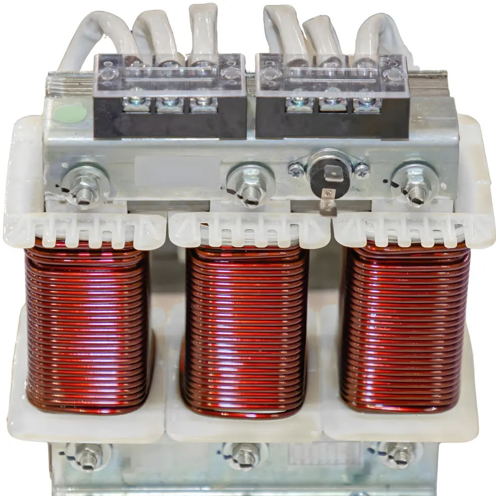
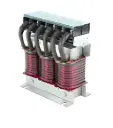
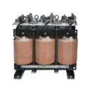
dv/dt Filters
A dv/dt filter is fitted on the output of a VFD/inverter to slow the voltage rise (dv/dt) of PWM pulses.
| Specifications | |
| Voltage Rating | 3PH - 400V to 690 |
| Max. Peak Voltage | <1000V |
| Typical dv/dt reduction | Factor 8 to 12 |
| Current Rating | 12 to 1100A |
| Voltage drop | <3V |
| Insulation Class |
F Class for dry type (H Class on request)
|
| Overload Capacity | 1.5× rated current for 1minute |
| Cooling | AN/AF |
| Motor Frequency | 0 to 60Hz (Up to 400Hz on request) |
| Applicable Standards | IEC 60076-6 (power reactors): temperature rise, dielectric, routine/type tests. |
| Certifications | CE ROHS |
- Essential for Long motor cables (tens–hundreds of meters) to limit surge/reflection at motor terminals
- To Protect motor insulation (PD risk) on older/reused or non-inverter-duty motors
- To reduce common-mode stress/shaft voltage when no sinusoidal output is needed
- Helps quick retrofit on existing VFDs where space/cost are tight (smaller than sine filters)
- Essential to meet basic OEM/utility dV/dt limits without full harmonic attenuation
- Helps lower EMI/RFI emissions enough for nearby instrumentation compliance
- Essential for marine/OEM skids with mixed cable types and unknown terminations
- Helps lower acoustic noise from PWM edge “buzz” in motors/piping
dV/dt Filters — Sizing Notes (Quick Guide)
- Purpose: Limit PWM edge steepness at the motor terminals to reduce insulation stress, ringing, and EMI.
- When to use: Cable lengths from ~25 m to 300 m+, older/non-inverter-duty motors, sensitive environments.
- Inputs needed: VFD VLL, motor current, cable length & type, carrier kHz, acceptable dV/dt at motor (e.g., ≤ 1–2 kV/µs).
How to size (rules of thumb)
-
Inductance target (LV drives): choose reactor so fundamental reactance ≈ 3–5% at 50/60 Hz per phase.
L≈XL2πf=(0.03 − 0.05) Vϕ/Irated2πfL \approx \dfrac{X_L}{2\pi f} = \dfrac{(0.03\!-\!0.05)\,V_\phi/I_\text{rated}}{2\pi f}L≈2πfXL=2πf(0.03−0.05)Vϕ/Irated - Carrier attenuation: aim for >50% reduction of edge rate at the motor; increase L for very long cables or high carrier (>6–8 kHz).
- Core choice: Gapped laminated core (most LV/MV) or air-core (zero saturation, larger size). Always gap iron cores for linearity.
- Thermal/derating: rate for RMS with harmonics (crest factor 1.8–2.2 typical). Check hot-spot at 40–50 °C ambient.
- Voltage drop impact: 3–5% X at fundamental → small efficiency hit; verify motor starting margin.
- Common-mode (optional): add a CM choke if bearing currents/EMI are concerns.
Spec line (example)
- “dV/dt Output Reactor, 415 V, 75 A, 5% X @ 50 Hz, 0.55 mH/phase, Class F, gapped iron-core, ΔT ≤ 80 K, audible noise ≤ 65 dB, designed for motor lead 150 m, carrier 4 kHz, dV/dt ≤ 1.5 kV/µs at motor.”
Installation Notes
- Place filter near the VFD (default). For very long runs, evaluate locating near the motor (case by case).
- Keep lead dress short & symmetrical; bond enclosure well to reduce EMI.
- Verify inverter carrier and min. load settings recommended by the filter vendor.
- Check temperature rise after first run (thermal imaging); re-tighten terminations.