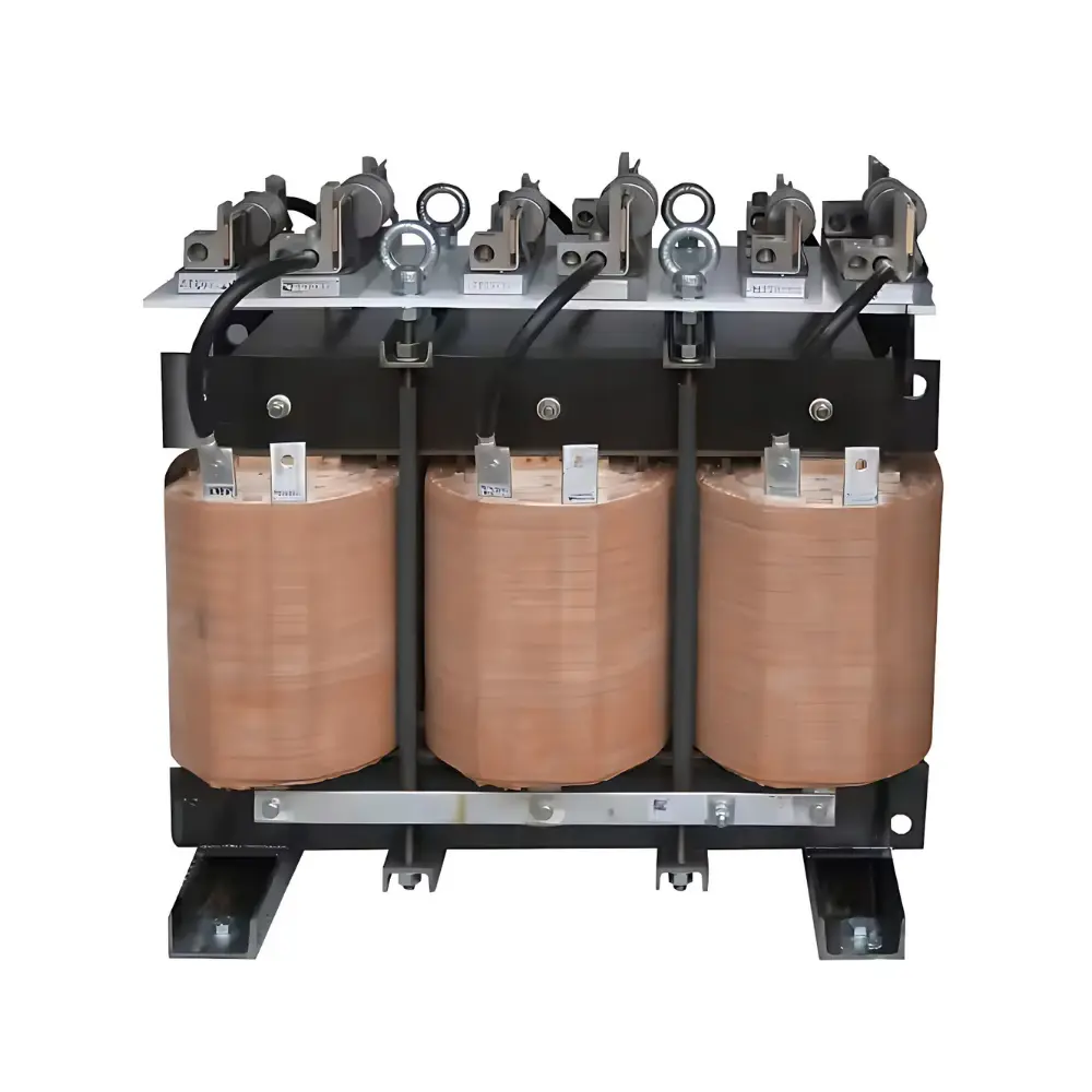
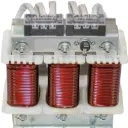
Detuned Reactors
Detuned reactors are series inductors installed with power-factor-correction (PFC) capacitor banks to deliberately shift the bank’s natural resonance below the 5th harmonic.
| Specifications | |
| Voltage Rating | 400V to 690V |
| Power Rating | 2.5KVAr to 100KVAr (Higher on request) |
| Insulation Class |
F Class for dry type (H Class on request)
|
| Cooling | AN/AF |
| Applicable Standards | IEC 60076-6, IS5553 |
| Certifications | CE ROHS |
- Drive-heavy industries (steel, cement, paper, textiles, plastics): protect PFC capacitors under 5th/7th harmonics.
- Data centers & telecom (UPS-rich feeders): keep kvar banks stable and cool.
- Commercial campuses (malls, hospitals, airports, IT parks): avoid resonance and nuisance tripping.
- Water & wastewater plants (pump VFD clusters): maintain PF without harmonic amplification.
- Generator/weak grids (DG/CPP/microgrids): improve stability; prevent cap over-voltage.
- Crane/hoist/elevator groups: handle rapid load swings with drives; reduce voltage flicker issues on PFC banks.
- Retrofits of failing PFC panels: replace plain caps with detuned sets to stop frequent capacitor/breaker failures.
What they do?
- Series reactors used with capacitor banks so the L–C branch resonates below the 5th harmonic, preventing harmonic overcurrent/overvoltage on capacitors and avoiding feeder resonance.
When to use
- Plants with VFDs, welders, furnaces, drives-dominated HVAC, cranes/elevators.
- Utilities/specs that mandate PF despite high background THD.
- LV APFC panels and MV banks (11/22/33 kV) where resonance risk is non-negligible.
Sizing quick-guide
-
Choose a detuning percentage p% (reactor X at 50 Hz as % of capacitor |X|):
- 5.67% → ~210 Hz (≈ 4.2nd)
- 7% → ~189 Hz (≈ 3.78th) (most common)
- 14% → ~134 Hz (≈ 2.68th) (very dirty systems / weak grids)
-
Tuning
frequency: f_t = f₁ √(1/p) with
f₁ = 50 Hz
-
Inductance per phase
(given capacitor C): L = p / ((2π f₁)² ·
C)
Important effects (design around these)
• Capacitor terminal voltage rises: Vcap ≈ Vbus / (1 − p) → use higher-voltage caps (e.g., 440–480 V on 415 V at 7%).
• Net kvar delivered to bus drops: Qbus ≈ Qcap (1 − p) → a 100 kvar step gives ~93 kvar at 7%.
• Thermal current includes fundamental + residual harmonics → rate reactors and capacitors for RMS with THD.