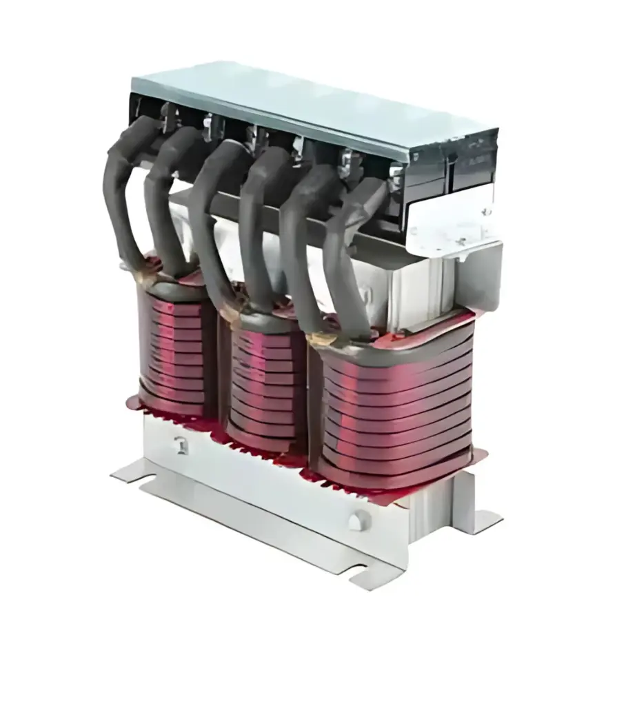
Sine Wave Filters
A sinewave filter converts the PWM output of a VFD/inverter into a near-sinusoidal waveform.
| Specifications | |
| Voltage Rating | 3PH - 400V to 690 |
| Current Rating | 2.3 to 1000A |
| Insulation Class |
F Class for dry type (H Class on request)
|
| Overload Capacity | 1.5× rated current for 1minute |
| Cooling | AN/AF |
| Motor Frequency | 0 to 60Hz (Up to 400Hz on request) |
| Applicable Standards | IEC 60076-6 (power reactors): temperature rise, dielectric, routine/type tests. |
| Certifications | CE ROHS |
- Essential for very long cables / subsea / mines where near-sinusoidal voltage at motor is mandatory
- For Non-inverter-duty motors needing true sinusoidal terminal waveform (extend insulation/bearing life)
- Supports Multiple motors on one VFD to avoid cross-talk and uneven load sharing
- Essential for HVAC/data centers/hospitals to minimize conducted & radiated emissions into sensitive systems
- Help Reduce motor heating & acoustic noise for efficiency or comfort-critical sites
- Used in Long-distance pump/fan drives to eliminate standing waves and over-voltage entirely
- Helps Meet strict EMC/spec mandates (e.g., OEM export packages, naval/rail standards)
- Enable standard sine-rated contactors/relays on motor feeders without PWM stress
Sine-Wave Filters — Sizing Notes (Quick Guide)
- Purpose: Reconstruct a near-sinusoidal voltage/current so the motor “sees” a sine wave—ideal for very long cables, multiple motors per drive, and non-inverter-duty machines.
- When to use: Cable runs >100–150 m, multi-motor feeders, sites with strict EMC/acoustic limits.
What to target
-
Cut-off frequency (fc): set the L-C low-pass well below the PWM carrier but above fundamental.
Typical: fc ≈ 150–300 Hz (LV), 100–200 Hz (MV).
fc=12πLCf_c = \dfrac{1}{2\pi\sqrt{LC}}fc=2πLC1 - Inductance (L): often 5–7% X at fundamental per phase (higher than dV/dt filters).
-
Capacitance (C): choose so reactive current at 50/60 Hz is acceptable (commonly 3–8% of motor rated current).
Verify inverter can supply leading vars at light load. - Damping (R): include series/parallel damping (or C-type topology) to control peaking and avoid resonance with cable.
- Capacitor voltage rating: because of L–C interactions, use elevated LV ratings (e.g., 480–525 V caps on 415 V systems). MV caps per bank spec.
- Core choice: Gapped iron-core (compact) or air-core (no saturation, larger footprint).
- Thermal/derating: rate for harmonic RMS and ambient; verify audible noise limits.
Spec line (example)
- “Sine-Wave Filter, 415 V, 75 A, target fc = 220 Hz, X ≈ 6% @ 50 Hz, L ≈ 0.66 mH/phase, C ≈ 40 µF/phase (Δ), damped, dV/dt ≤ 0.5 kV/µs, THDV_VV at motor ≤ 5%, cable length 300 m, continuous.”
Installation Notes
- Place filter near the VFD (default). For very long runs, evaluate locating near the motor (case by case).
- Keep lead dress short & symmetrical; bond enclosure well to reduce EMI.
- Verify inverter carrier and min. load settings recommended by the filter vendor.
- Check temperature rise after first run (thermal imaging); re-tighten terminations.