Inverter & UPS Transformers
| Specifications | |
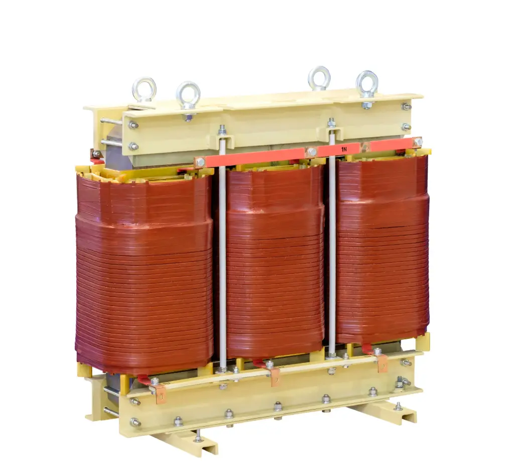
| Type | Dry Type (VPI/CRT) |
| Voltage Rating | Up 33KV |
| Power Rating | 1KVA to 630KVA |
| Insulation Class | F Class for dry type (H Class on request) |
| Cooling | AN/AF |
| Applicable Standards | IEC 60076, IS 2026 |
| Certifications | CE, ROHS |
- Data centers & IT: UPS & Inverter
- Transport & metros (indoor substations): Stations, tunnels, depots—aux/UPS supplies.
- PV inverters (C&I / rooftop / plant buildings): LV–LV isolation or step interfaces placed indoors.
- Wind turbine auxiliaries (nacelle/tower base rooms): UPS/inverter auxiliary transformers in enclosed spaces.
- Battery Energy Storage (BESS halls): PCS/UPS isolation inside battery rooms or power blocks.
- Microgrids & hybrid plants (indoor equipment rooms): Inverter couplers and UPS back-up transformers.
Refer our Blog: Inverter-Duty Transformers vs Ordinary Transformers: What Really Changes
What They Are?
Transformers engineered to interface power‑electronic converters (VFDs, solar/wind inverters, rectifiers) with the grid or load, handling high harmonic/RMS currents, dv/dt, possible DC bias, and special cooling/insulation needs while providing galvanic isolation and, when required, phase‑shift.
Where They’re Used?
• Solar PV inverter step‑up: 0.6–1.2 kV inverter output → 11/22/33 kV grid intertie (pad‑mount / indoor).
• Battery energy storage systems (BESS): bidirectional converters tied to 11/22/33 kV feeders.
• MV drive isolation: 3.3/6.6/11 kV drives feeding large motors (phase‑shifted multi‑pulse front‑ends).
• Industrial rectifiers/electrolysis: 6/12/24‑pulse supplies; harmonic control via vector group/phase‑shift.
• Microgrids & genset paralleling skids: isolation/earthing scheme change, fault containment.
Why They Differ From ‘Standard’ Transformers?
• Higher **RMS & harmonic currents**: sized for K‑factor / specified harmonic spectrum without excessive heating.
• Manage **dv/dt and common‑mode**: electrostatic screens and controlled stray capacitance to protect converters and loads.
• Possible **DC bias** from converter imbalance: core design to avoid saturation (air‑gap / zero‑sequence path where applicable).
• **Leakage reactance** tailored: supports converter commutation, limits fault currents, and shapes harmonic flow.
• **Phase‑shifted windings** (e.g., ±15°, 30°) for 12/24‑pulse rectifier/inverter arrangements to cancel selected harmonics.
• Robust **insulation & PD targets** (for dry‑type) and enhanced cooling (ONAN/ONAF or AF for dry‑type).