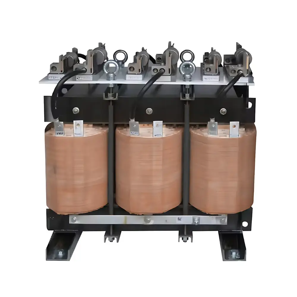
Series Reactors
A series reactor is a heavy-duty inductor installed in series with a feeder or equipment to add controlled impedance. It limits fault and inrush currents, damps harmonics/resonance, and stabilizes voltage during switching or load changes.
| Specifications | |
| Voltage Rating | 400 to 690V |
| Power Rating | 1 Amps to 1000 Amps |
| Insulation Class | F Class for dry type (H Class on request) |
| Cooling | AN/AF |
| Applicable Standards | IEC60289 |
| Certifications | CE ROHS |
Series input reactor (line reactor) — when to use
- Weak/“noisy” grids: limit inrush, commutation notching, and mains flicker into the VFD
- Reduce input current THD and meet basic utility limits without a full AFE or passive filter
- Protect rectifier bridge from voltage dips, transient surges, and short-circuit stresses
- Share fault energy with upstream gear; helps avoid nuisance trips on DC-bus overvoltage
- Stabilize DC-bus on multi-drive buses or genset supplies
Series output reactor (load reactor) — when to use
- Moderate cable lengths (≈ 25–150 m): soften PWM edges enough to cut ringing and over-voltage at the motor
- Older / non-inverter-duty motors: lower dV/dt and bearing stress without a full sine-wave filter
- Multi-motor on one drive (short runs): improve current sharing and reduce cross-talk
- Reduce motor audible noise and heating vs bare PWM, at lower cost/size than a sine-wave filter
Input Line Reactors (VFD input, series)
- Purpose: Limit notching/inrush, tame mains flicker, protect rectifier bridge, reduce input THD.
- Where used: Weak grids, gensets, multi-drive buses, long MV/LV feeders.
- Quick sizing: 3–5 % X at 50/60 Hz (per phase).
- Benefits: Smoother DC-bus, fewer over-voltage trips, better diode/IGBT life.
- Notes: Place upstream of VFD; verify breaker/relay settings with added X; check temperature rise at full harmonic RMS current.
- Standards: IS/IEC 61800-3 (EMC for PDS), IS 2026-6 (MV reactors) / IS/IEC 61558-2-20 (LV small reactors).
Output Load Reactors (VFD output, series)
- Purpose: Soften PWM edges, reduce ringing and over-voltage at motor, cut motor noise/heating.
- Where used: Moderate cable length (≈ 25–150 m), multi-motor feeders, older motors.
- Quick sizing: 3–5 % X at fundamental.
- Benefits: Lower dV/dt, improved current sharing, less EMI than bare PWM.
- Notes: Place near VFD by default; ensure motor voltage margin (voltage drop ≈ X%); gap iron cores for linearity; consider CM choke if bearing currents are a concern.