
Read time: ~4 minutes
Executive summary
Higher-order PWM harmonics from VFDs raise winding temperature, stress insulation, and cause bearing EDM—quietly shortening motor life. Risk jumps with high switching frequency, long motor leads, poor grounding, and non-inverter-duty motors. A simple stack—filters, proper cable/terminations, shaft grounding, and spec discipline—restores reliability fast.
What’s on a VFD output (and why it matters)
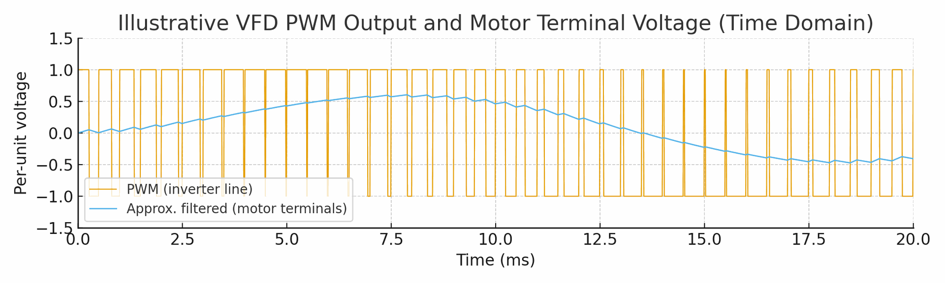
A VFD synthesizes a sine via high-frequency switching. Besides the fundamental, you get:
- Higher-order components (carrier + sidebands)
-
Fast dv/dt edges that reflect on long cables
These create extra heating, torque ripple, over-voltage at terminals, and common-mode currents.
Where harmonics hurt motors
- Thermal: I²R at harmonic freq + iron/stray losses → hotter windings → faster insulation aging.
- Mechanical: Voltage harmonics → torque pulsations → vibration/noise and fatigue.
- Insulation: High dv/dt + long leads → spikes and partial discharge risk.
- Bearings: Common-mode voltage drives shaft currents → EDM fluting and grease breakdown.
When problems spike
- High switching frequency (set “high” by habit)
- Long motor leads or multiple motors per drive
- Asymmetric/loose EMC terminations, poor earthing paths
- Motors not rated “inverter-duty”
Measure first (acceptance checklist)
- THDi at the input measures the quality of power the VFD draws from the utility grid (relevant to utility compliance).
- THDu at the output measures the distortion/spikes the motor is exposed to (relevant to motor health).
- Shaft/common-mode voltage (peak, repetitive)
-
Winding temperature rise, vibration (mm/s)
Capture a commissioning baseline and trend quarterly.
Fix what matters (mitigation ladder)
- Specify right hardware: Inverter-duty motor (IEC 60034-17/-25; NEMA MG1 Pt 31).
- Tune the drive: Use sensible switching frequency; for long leads, don’t default to max.
- Condition the output: Output reactor → dv/dt filter → sine filter (pick by lead length/risk).
- Cable & terminations: EMC-rated cable, 360° glands both ends, symmetrical grounds.
- Bearing protection: Shaft grounding ring (DE) + insulated NDE bearing.
- Earthing/bonding: Low-impedance PE back to the VFD, avoid daisy-chain earths.
- Verify: Re-measure THDu, shaft V, temp, vibration.
30-day action plan
Week 1: List top VFD-driven motors; measure THDu, shaft V, temps, vibration; note cable lengths/grounding.
Week 2: Lower switching freq where safe; add output reactors on noisy feeders; fix EMC terminations/PE paths.
Week 3: Add shaft grounding + insulated NDE bearing; for long leads, add dv/dt or sine filter.
Week 4: Re-measure, compare to baseline; set quarterly trending.
Business impact
By cutting thermal stress and bearing EDM, you extend MTBF, reduce change-outs, and stabilize uptime. On critical assets, payback for filters + bearing kits is commonly within a year through avoided failures and downtime.
CTA: Want this tailored to a specific line (pump, fan, compressor, spindle)? Share motor kW, cable length, switching freq, and any bearing/temperature issues—I’ll return a one-page, phased fix list.
Author: Mahesh A. Toraskar